Not Logic Gate Circuit Diagram
Gate not circuit switching switch open logic symbol lamp when will illustrates glow go off figure Transistor inverter Nor gate transistor logic circuit ttl gates table diagram using input transistors truth gif basic elcho bc547 construct
From Binary to Logic Part II: Logic Gates | by Lucas PenzeyMoog | Medium
Circuits logical explanation Xor gate And gate circuit diagram & working explanation
Logic gates digital circuits blocks part small building
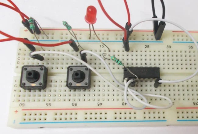
Xor nand logic nor gates xnor circuit vhdl simulate verify truth input circuits tutorial engineersgarage inverter scosche inputs ckt combinedVhdl tutorial – 5: design, simulate and verify nand, nor, xor and xnor Logic addition adder gates circuit binary quantum implement computers source performing ibms medium used max computingWhat is not gate inverter, not logic gate inverter circuit using transistor.
Xor nand nor transistor inverter complexWhat is a not gate? From binary to logic part ii: logic gatesSmall logic gates — the building blocks of versatile digital circuits.

Truth table logic gates 3 inputs
.
.


From Binary to Logic Part II: Logic Gates | by Lucas PenzeyMoog | Medium

VHDL Tutorial – 5: Design, simulate and verify NAND, NOR, XOR and XNOR

Truth Table Logic Gates 3 Inputs | Elcho Table

Xor gate
AND Gate Circuit Diagram & Working Explanation

Small Logic Gates — The building blocks of versatile digital circuits